
In the first part of this series, we could already read between the lines. Software and firmware development for embedded devices – and in our case, constrained devices with low performance – can be very complex. We can especially see this in C/C++ where developers are confronted with challenges at the bottom of the development stack. Cross compilers and linkers, libraries, include paths and build/flash tools need to be selected and installed, often depending on the underlying hardware. A cross-toolchain for an Arduino with Atmel AVR processor is not the same as the one for ARM Cortex M. Wouldn’t it be great to have a tool that takes care of this?
PlatformIO does exactly this work for the developer; It currently knows 24 development platforms for embedded (e.g. Atmel AVR, Espressif8266,…), 15 embedded frameworks (e.g. Arduino, ARM mbed,…), over 470 boards (“Arduino UNO”, “NodeMCU ESP8266”,…) and thousands of libraries and example. That should make for an easy start!
Integrated into the development environment
PlatformIO (PIO) can be installed and operated in different flavors. On the one hand, PIO Core allows you to do everything from the command line. This is useful for developers who feel comfortable on the shell level. It is also very handy for use with cloud IDEs, but we’ll talk about this in a later part of our IoT series.
PIO comes with integrations for various IDEs, and the rest of the series uses Visual Studio Code from Microsoft. It is very popular in the developer community due to its open architecture regarding extensions. A click on the icon for extensions in the left menu line and entering “platformio” in the search field leads with the first hit to the official PIO-VS code extension, after a click on “Install”, it is available.
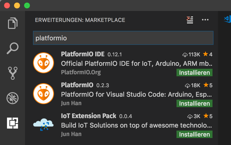 Figure 1: Installation of PIO plugins within VSCode
The core of PlatformIO is based on Python 2.7, which is part of the standard repertoire under MacOS and Linux. Windows users may need to reinstall Python, but this is automated by the PIO installer and well documented on the PlatformIO website. Furthermore, the installation of C-compilers like clang under MacOS may be necessary.
After starting VSCode you will be welcomed with the PIO Home Screen, at least as long as you have selected the checkmark “Show at startup” (Figure 2).
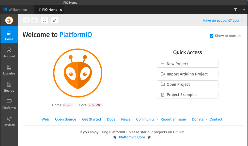 Figure 2: All Functions within PlatformIO Homescreen
The home screen combines all the functionalities offered by PlatformIO Backend: Manage your account data (optional), search for boards, libraries, platforms, search for connected devices and manage projects.
Boards & frameworks
For our training workshops as well as for the following examples of this series, we will use the board “NodeMCU 1.0” with an ESP8266 processor. The ESP8266 is a very cheap WiFi-SoC from Chinese company Espressif Systems, which support the espressif-own embedded framework. It also has a port of the Arduino framework, so most of the “sketches” known from Arduino also work with this board. Communication is possible with its built-in WiFi connectivity, IoT solutions with MQTT, CoAP or HTTP.
You can use the Board Explorer (Figure 3, click on the “Boards” icon in PIO Home) to see if your own board is supported by PlatformIO. With over 470 boards currently supported, the probability of this is fairly high.
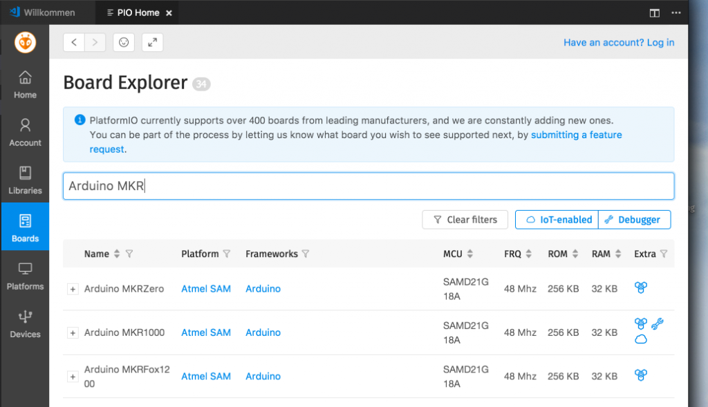 Figure 3: Finding one’s own board
After entering the board name you can quickly find your own board. The table shows the supported platforms, frameworks and some technical data of the board. Each board has a board ID, which is visible on the “+” icon after opening the entry. This board ID becomes relevant for project creation and can be copied to the clipboard.
A similar search for embedded platforms is also available by clicking on “Platforms”. The cross-linking between boards, platforms and frameworks allows you to check which implementation options you have. Links lead to manufacturer documentation or source code repositories (Figure 4)
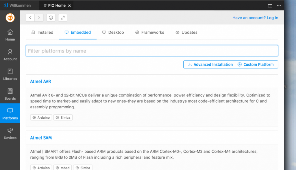 Figure 4: Explore Embedded Frameworks
First example project
Normally, you create a new project via the PIO Project Wizard. After clicking on “New Project” in the home screen, the wizard opens and asks for the minimum conditions required for creating a project: Which board should the project work for, and with which embedded framework should it work? The first choice determines the compiler toolchain to be installed.
For ESP8266, this is the toolchain for the xTensa processors (the ESP8266 is a Tensilica xTensa) with the so-called Esptool for flashing. The latter choice of framework determines where the framework code is to be downloaded from. In our case, it is from the Github repository of Espressif System. PlatformIO will automatically install the toolchain and frameworks in a user’s local home directory and make them available in both the IDE and the command line. This is an enormous simplification and acceleration, especially when changing boards or platforms!
To start as quickly as possible with functional code, we select an example by clicking on “Project Examples”. PIO has examples of different platforms, and the Arduino area is abundant (Figure 5).
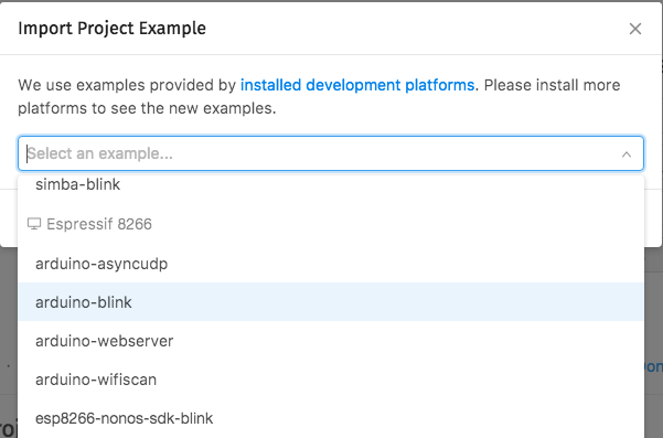 Figure 5: Selection of a sample template
The examples are sorted by platform. As a simple starter example, we select the example “arduino-blink” in the category “Espressif8266”. A click on “Import” creates the project and opens it in the VSCode Explorer.
For PlatformIO, a project is located in a directory containing all sources, dependent libraries, settings for the selected framework/board (“environment”) and the compiled binary code. A suitable .gitignore is included that excludes directories with binary files or local IDE settings.
The source code “Sketch” can be found in src/main.cpp. The Arduino framework is implemented in C++ and provides classes with a degree of abstraction for many functionalities that make it easier to get started. Even those who have not yet programmed or not programmed much in C/C++ should get along well here. (And, yes, behind every C statement there needs to be a semicolon 🙂
Listing 1 shows the generated example:
#include "Arduino.h"
void setup() {
  // initialize LED digital pin as an output.
  pinMode(LED_BUILTIN, OUTPUT);
}
void loop() {
  // turn the LED on (HIGH is the voltage level)
  digitalWrite(LED_BUILTIN, HIGH);
  // wait for a second
  delay(1000);
  // turn the LED off by making the voltage LOW
  digitalWrite(LED_BUILTIN, LOW);
   // wait for a second
  delay(1000);
}
The sketch is divided into two sections. The setup() function is called once when the board is initialized. It contains code that makes certain board preparations. In the example, the I/O port for the LED (“LED_BUILTIN”) permanently installed on the board is set to “OUTPUT” via “pinMode” – to be able to switch the LED.
The loop() method is called continuously by the Arduino Framework, which expects the function not to block for a long time but to return to be called again. In the example, “digitalWrite” sets the LED to “HIGH” or “LOW” to switch it on and off. (Tip: the permanently installed LED on the NodeMCU is inverted, HIGH switches it off, LOW switches it on.) In between, wait with “delay”.
At this point, we extend the sketch by a program output on the serial interface, so an “embedded logging in simple”. The matching C++ class in the Arduino framework is called “Serial” and is predefined. It offers several functions for output from the first serial port wired to the USB cable on most (Arduino-compatible) boards.
void setup() {
  // initizalize Serial with 9600 bps
  Serial.begin(9600);
  pinMode(LED_BUILTIN, OUTPUT);
}

void loop() {
  // send something..
  Serial.print(".");
  digitalWrite(LED_BUILTIN, HIGH);
  delay(1000);
(…)
Listing 2 shows the extensions. In the setup() function the serial port is initialized with 9600 bits/s (Serial.begin); in the loop() function we send a dot every time the function is entered.
Compile, flash, monitor
The next step is to bring the code on the board to life. The PIO extension displays several action buttons in the lower left corner of the PC code icon bar (Figure 6). The names of the functions can be displayed by hovering from left to right: compilation problems, PIO home, build (compile/link without flashing), upload (build with flashing), upload to remote device (flashing over a network), clean (corresponds to a make clean), test, run task, serial monitor and terminal.
![]() Figure 6: Action buttons within the command pane
Figure 6: Action buttons within the command pane
By clicking on the arrow (“Upload”) the current project is compiled, linked to a firmware binary and uploaded to the device connected via USB, i.e. written to the flash memory there. PlatformIO recognizes the connected boards by their signature. They can also be displayed on the PIO home screen at any time by clicking on “Devices”. Under Linux and MacOS, the ports are identified with a file in /dev (e.g. /dev/cu.SLAB-USBtoUART or /dev/ttyUSB0). Under Windows they are managed as the known COM:xx ports. As long as only one board is connected, no further query is required. PIO simply uses this one board for the upload command.
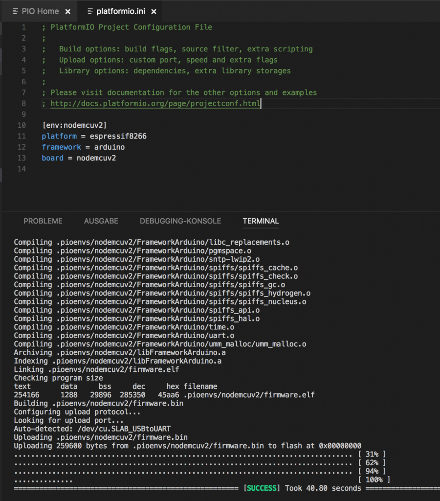 Figure 7: Compile and Upload
Figure 7 shows the file platformio.ini in the upper text window. It contains the definition of the environments, the combinations of board and framework, together with specific settings. The example contains several environments. For our example, we remove everything except the section [env:nodemcuv2]. A tip for the ESP8266 at this point is to add the line “upload_speed = 921600” to the end; this substantially accelerates the flashing process.
After clicking the Upload button in the icon bar, a terminal window opens and shows the compile, link and upload process. After successful flashing, the board starts flashing according to the sketch. How do we get our debug output? A click on the connector icon (Serial Port Monitor) opens another terminal window with an instance of miniterm, which opens with the USB port and the basic settings 9600bit/s 8N1. As in the sketch, you can see a dot on the output every 2 seconds.
Build system
PlatformIO provides its user with a very good abstraction to the underlying build system. As a developer you don’t have to deal with makefiles, link settings and other things, because PIO covers many build steps by using SCons. In the following article, the parts under the hood will be examined more closely.
To access the various functions of the build system from the IDE, simply click on the “Run-Tasks” icon. It opens a list of tasks that basically correspond to the targets of the build systems, e.g. “Clean” to delete build artifacts. Command line friends can open a terminal in the icon bar and use the “pio run –target clean” command to do the same.
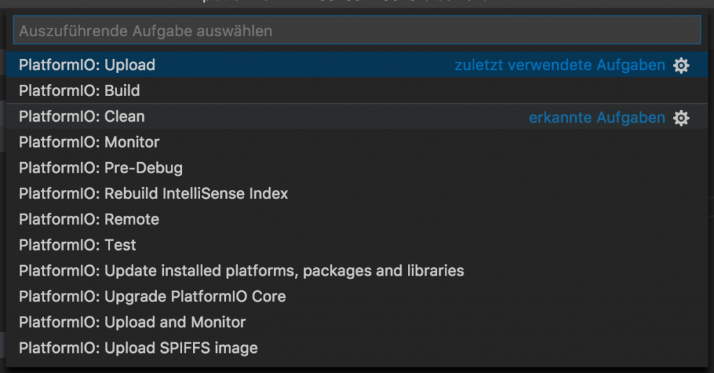 Figure 8: Compile and Upload
Bottom line
The steps shown here are sufficient to take the first steps with your own embedded board away from manufacturer-specific development environments. PlatformIO offers access to numerous development frameworks and boards. SCons has a very powerful build system with many functions. We will go over SCons in greater detail in the next article in the IoT series. These include going over all the work that is necessary in distributed teams for modern, agile development; integration in code repositories; continuous integration and delivery environments; as well as the possibility to test code automatically.
IoT Conference 2020 – Program
● Deep Learning for IoT Devices
● Real Time Analytics on the Edge and in the Cloud with Azure IoT