

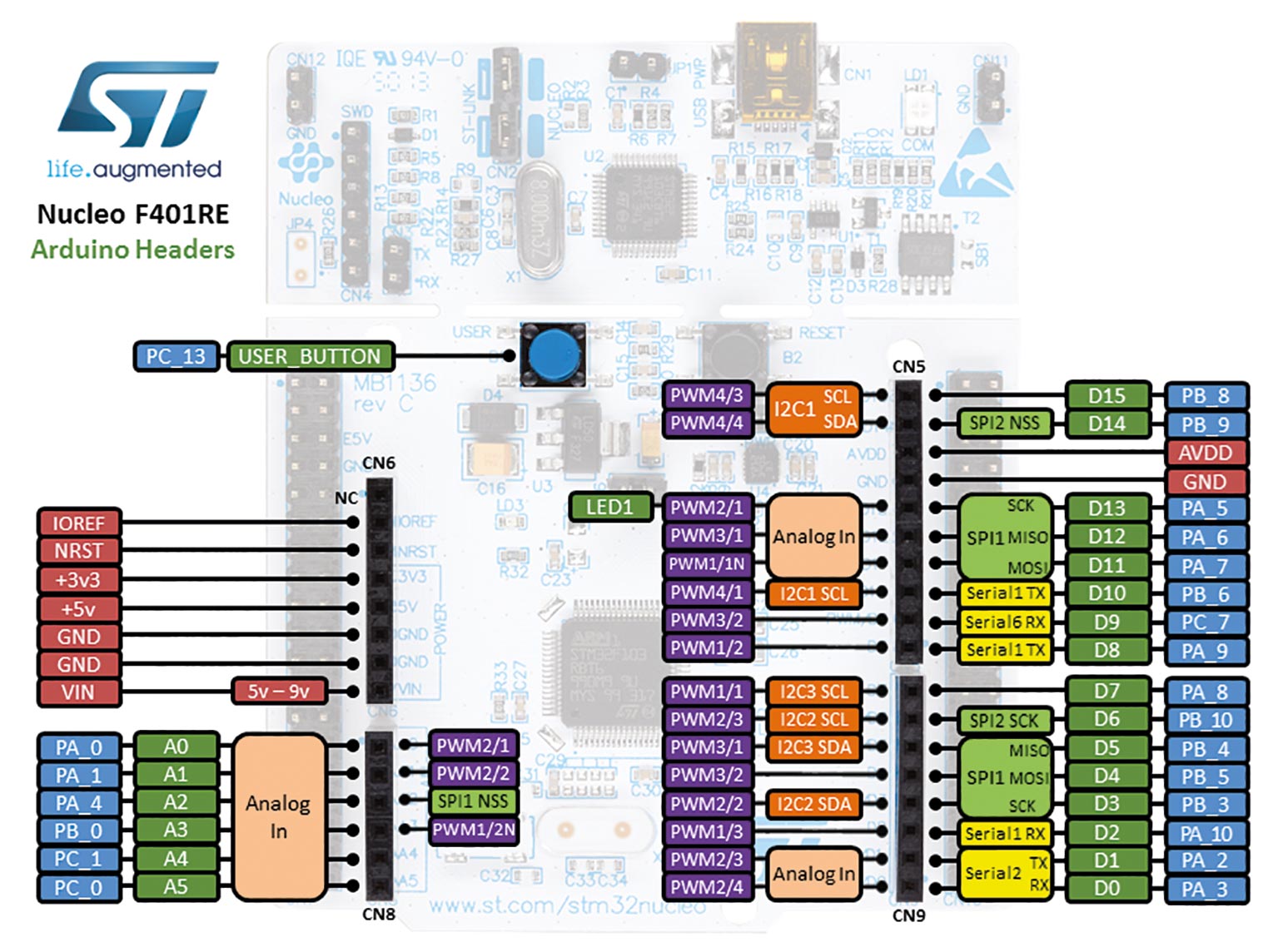
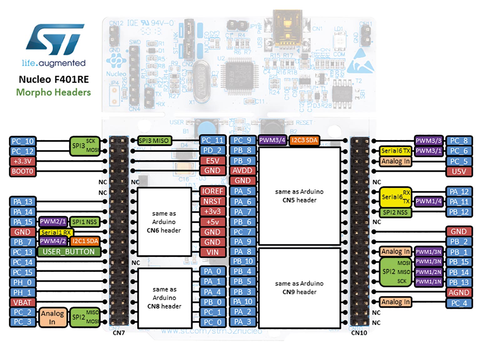
The microcontrollers in the STM32 family are characterized by high computing power and a large number of I/O pins. Special development boards such as the Nucleo F401RE, which can be purchased for around 24 euros, are available to get started with programming. If you take a look at a pinout of the board (Fig. 1 and 2), you will immediately notice that the Nucleo F401R is pin-compatible with the Arduino. This means that all shields that are available for the Arduino can also be used for the Nucleo. Of course, the Nucleo board has considerably more interfaces than the standard Arduino. A technical data overview can be seen in Table 1.
| Housing LQFP64 |
| ARM 32-bit Cortex-M4 CPU with FPU |
| 84 MHz CPU |
| Operating voltage 1.7 V to 3.6 V |
| 512 KB Flash |
| 96 KB SRAM |
| 50 x GPIOs |
| 16 x 12 bit AD converter |
| Real-time clock |
| Extended timer functions |
| 2 x watchdog timer |
| 4 x USART/UART |
| 3 x I2C |
| 3 x SPI |
| SDIO |
| USB 2.0 |
The development environment: STM32CubeIDE
Great hardware is only one success factor during development, a well-tuned IDE for hardware is a much more important point. For the microcontrollers of the STM32 family, there is a whole range of development environments – from very expensive to free-ware, everything is available. In this article, we use the STM32CubeIDE. It can be downloaded for free and is available for Linux, Mac, and Windows. However, you have to give your email address to start the download. But this is a small price to pay, considering how powerful the IDE is. Linux installation runs entirely on the command line and can be done without any problems. Under Linux, however, the installation must be run with root permission.
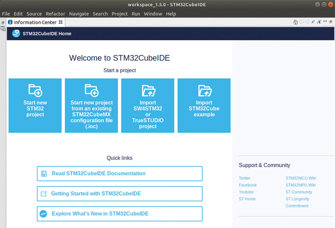
After installation, the IDE can be started comfortably from the application overview. If you do not see the IDE right away, just search for STM. At first start, the STM32CubeIDE asks where the workspace should be created. After that, the IDE presents itself as shown in Figure 3.
Now, we connect the Nucleo board via USB to our PC so that we can start with the first small test. To do this, click Start new STM32 project in the STM32Cube IDE. A window opens where we can select the STM32 target system. The family of STM32 microcontrollers is large, with 1796 different boards at the time of writing. To quickly find the Nucleo board, click on the Board Selector tab, select Nucleo-64 for the type, and scroll down the list until you see the NUCLEO-F401RE board. With one click, we select the board as the target system for our project. In the next step, we are asked to name the project and decide upon Blink. The options can be left at the preselected values. If we click the Finish button, the project will be created. Then, answer the questions about initializing the periphery and the perspective with yes. It takes a moment for all necessary project files to download. This is a good time to make a cup of coffee. When all components for the project are installed, the Pinout & Configuration screen opens as shown in Figure 4.
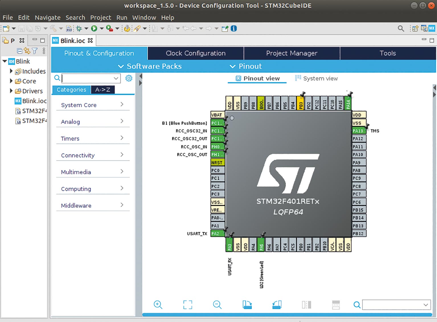
To understand what we are seeing on the screen right now, we have to backtrack a bit. The microcontrollers in the STM32 family are extremely versatile and configurable within wide limits. This means we can freely select the function for each pin of the controller. We are not only talking about input and output, but also about different interfaces (such as I2C, SPI and UART) and special functions that can be assigned to the individual pins. Explaining all existing possibilities would take too much space here.
You can take a look at the individual categories on the left to get an idea of what can be set. For us, the only important thing at the moment is that the green LED of the Nucleo board is connected to pin PA5. For now, the hardware configuration is complete. We can now start writing the actual program for the STM32.
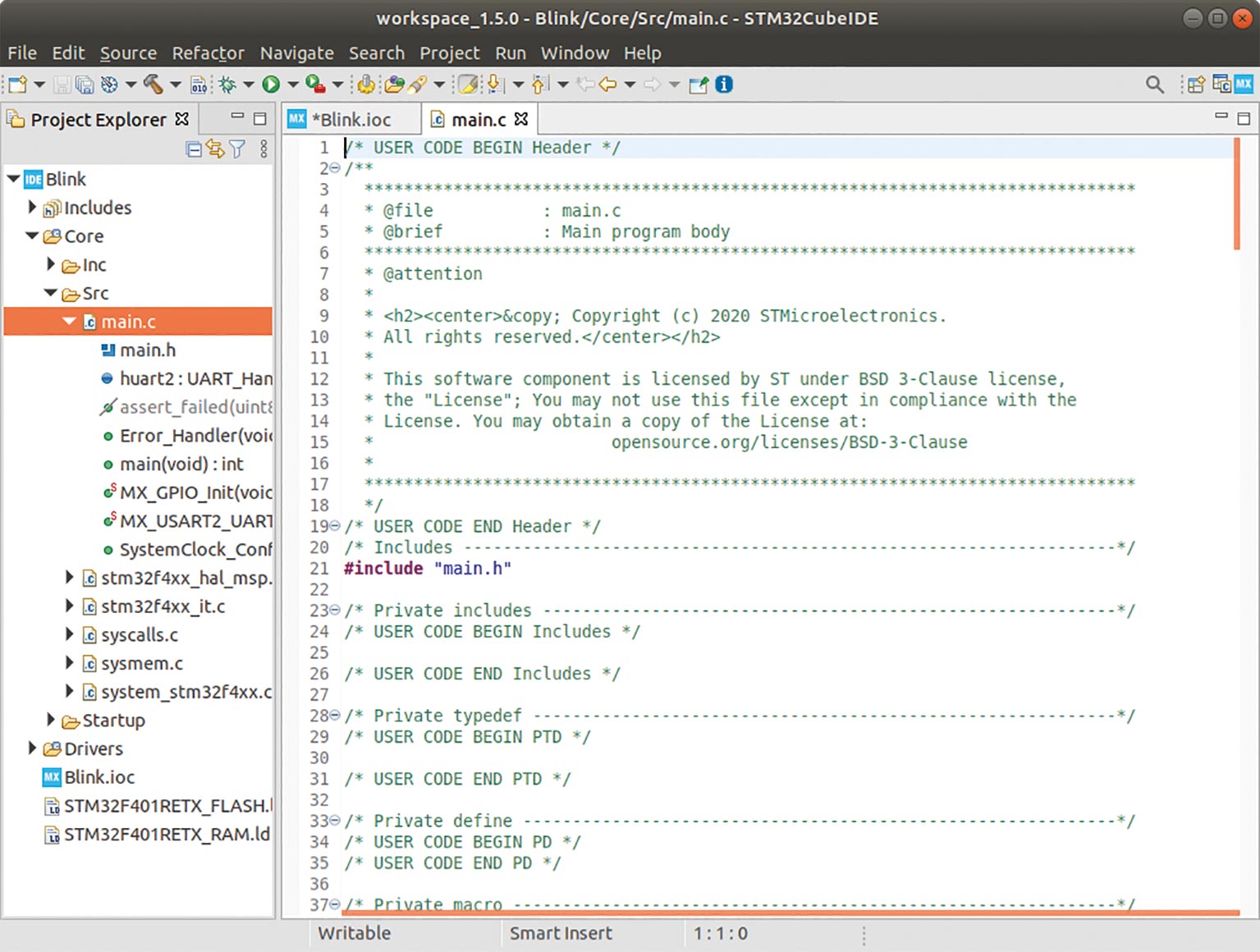
To do this, we open the file main.c. You can easily find the file by clicking on the tree structure in the project explorer (Fig. 5). Already with the first look into the source code you will notice that there are certain areas for user code. Use only the designated areas for user code to write your own programs. If you create code outside these areas, it will be overwritten by the IDE without mercy. Also, don’t change the existing comments, that will cause a lot of trouble. If you want to change something in the hardware configuration later, don’t do it in the code, but always via the configuration functions shown at the beginning (Fig. 4). You must always keep in mind that large parts of the source code are generated automatically. Of course, this only works if you don’t disturb the code generator.
Now we come to our first small program. This program makes the LED on the Nucleo board blink every second. Look for the area in the main.c file that is intended for the user code. Here, insert the lines as shown in Listing 1. You can use the comments as a good guide.
To load the code into the controller and run it, click on the Run icon (white arrow pointing right in the green circle). The first time we do this, we are asked a few questions, all of which can be answered with yes. After a short moment, the program is in the controller and will be executed.
Listing 1: Simple blink program
/* Infinite loop */

/* USER CODE BEGIN WHILE */

while (1) {

HAL_GPIO_TogglePin (GPIOA, GPIO_PIN_5);

HAL_Delay (1000);

/* USER CODE END WHILE */
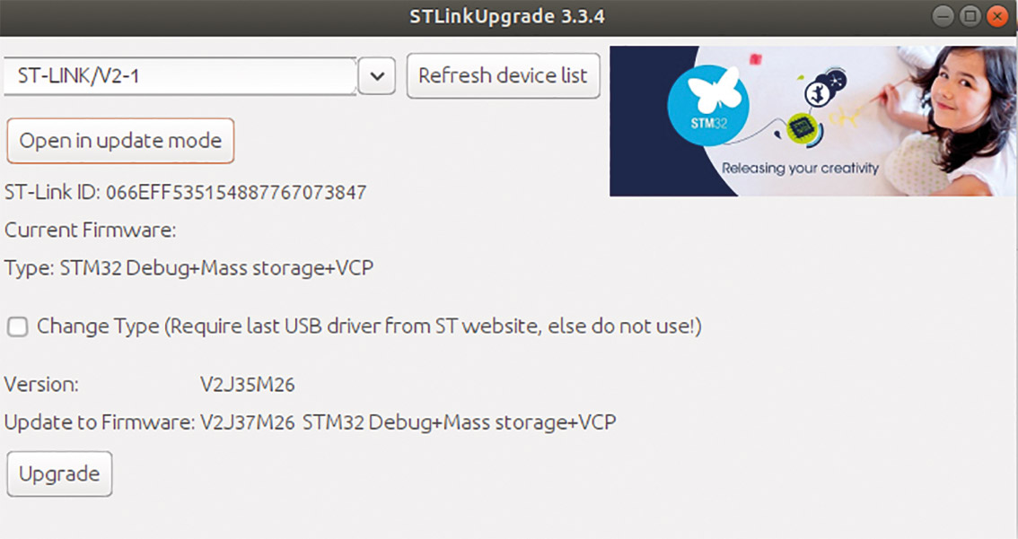
When uploading the software to the controller, it’s possible that the controller firmware is older than the IDE expects. Then, after some errors, you will end up in the dialog from Figure 6. First, click Open in update mode and then Upgrade to bring the firmware in your controller up to date. After the upgrade, you can try again to load the program into the controller.
We have shown in fast-forward how to create a program for the STM32 Nucleo F401RE board and load it into the controller. We have only gone into absolutely necessary points, and did not show many useful functions. If you want to learn more about STM32, you can start with the STM32 Wiki. Here many basic functions of the microcontroller are described in an easy-to-understand way. In the following sections, we will look at how to make the STM32 controller Internet-capable and how to build a simple web server on the controller.

WIZ5500 Ethernet Controller
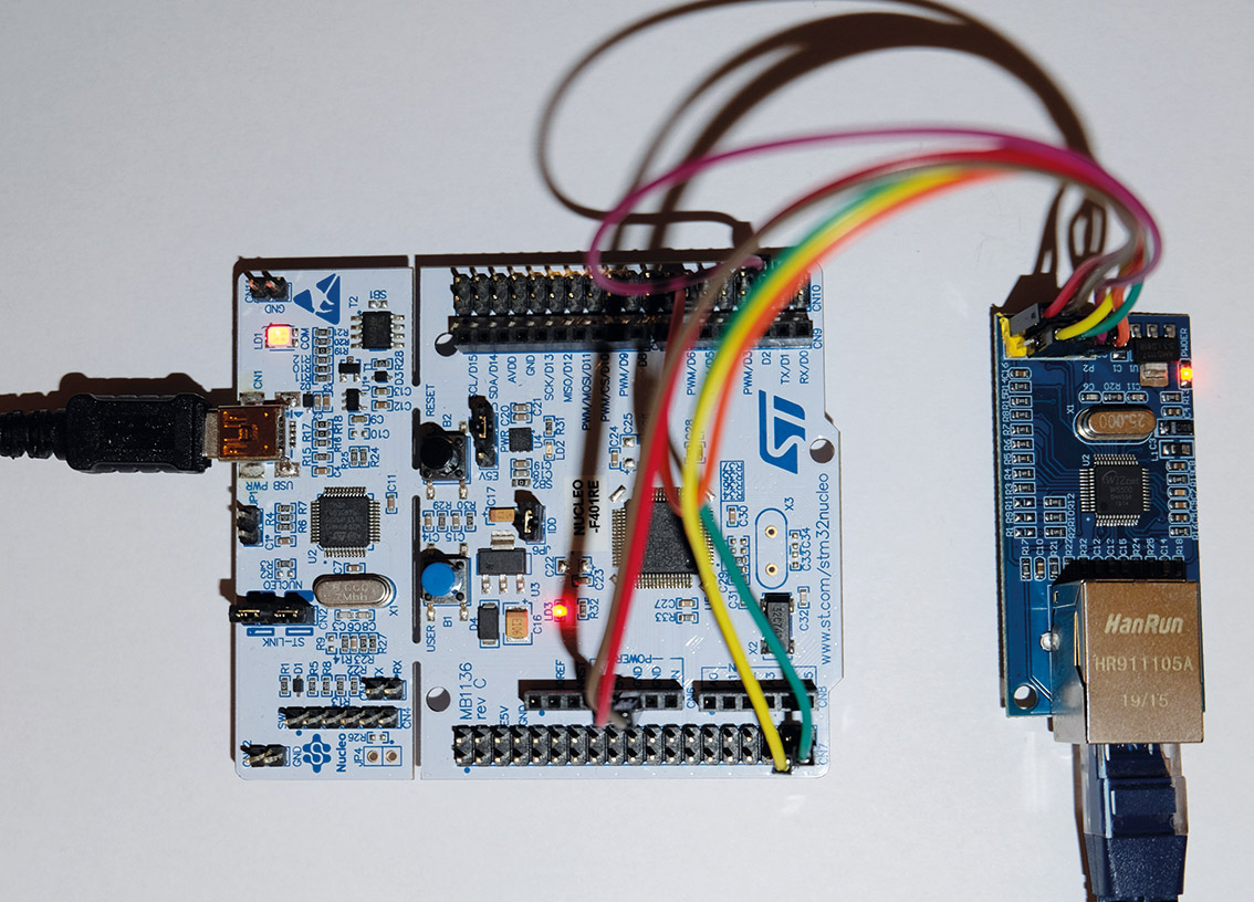
In order to connect the Nucleo board to a network, we first need a suitable interface. The WIZ5500 is a hardware Ethernet controller that supports the usual protocols such as TCP, UDP, ICMP, IPv4, ARP, IGMP, and PPPoE. Its operating voltage is 3.3 volts. The Ethernet controller operates at both 10 Mbit and 100 Mbit. As a hobbyist-friendly module, the WIZ5500 costs about 9 euros. The data transfer between the network module and the Nucleo board is done via the SPI interface. This is often used for the communication of microcontrollers with their peripherals. In principle, the data is transmitted clock-synchronously and serially. Table 2 shows how the Nucleo Board must be connected to the network module. It should be noted here that we are using the SPI2 interface of the Nucleo board. Figure 7 shows how to make the connections. To make sure we don’t forget later, we should connect the LAN directly as well. It wouldn’t be the first time that we spent hours looking for a fault—and in the end, it was only a forgotten plug connection.
| 5V | 5V |
| PC2 | MISO |
| PC3 | MOSI |
| PB10 | SCLK |
| PC4 | SCS |
| GND | GND |
The WIZ5500 module does not have its own Media Access Control (MAC) address. This means that the MAC must be provided externally. There are two possibilities here: For testing, just take any random sequence, because it would be quite unlikely to hit a MAC that you already have in your own network segment. The second option is to buy a chip that contains a MAC (globally unique). You read this and use it for the WIZ5500. The 24AA025E48 is for example such a chip.
For simple experiments, the first variant is absolutely fine because the MAC address only has to be unique within one network segment. The MAC is not transmitted across router boundaries. If you want to know even more about the WIZ5500 chip, take a look at the data sheet.
Library setup
The manufacturer of the WIZ5500 chip provides a special library for control. This offers us the possibility to set TCP IP parameters via simple API calls and to build a complete web server. The library can be freely downloaded from GitHub. Via the direct download link, you can download a ZIP archive that contains all the necessary files.
We unpack the archive into a directory below the src folder in our project. This is necessary because the library is available as a source and must be compiled together with the project in any case. In the unpacked files in the Ethernet subdirectory we find a file wizchip_conf.h. In this file, we have to select the chip 5500 in line 75 and save the file (Listing 2).
Listing 2: Select the WIZCIP 5500 in the config file of the library
#ifndef _WIZCHIP_

#define _WIZCHIP_  W5500   // W5100, W5100S, W5200, W5300, W5500

#endif
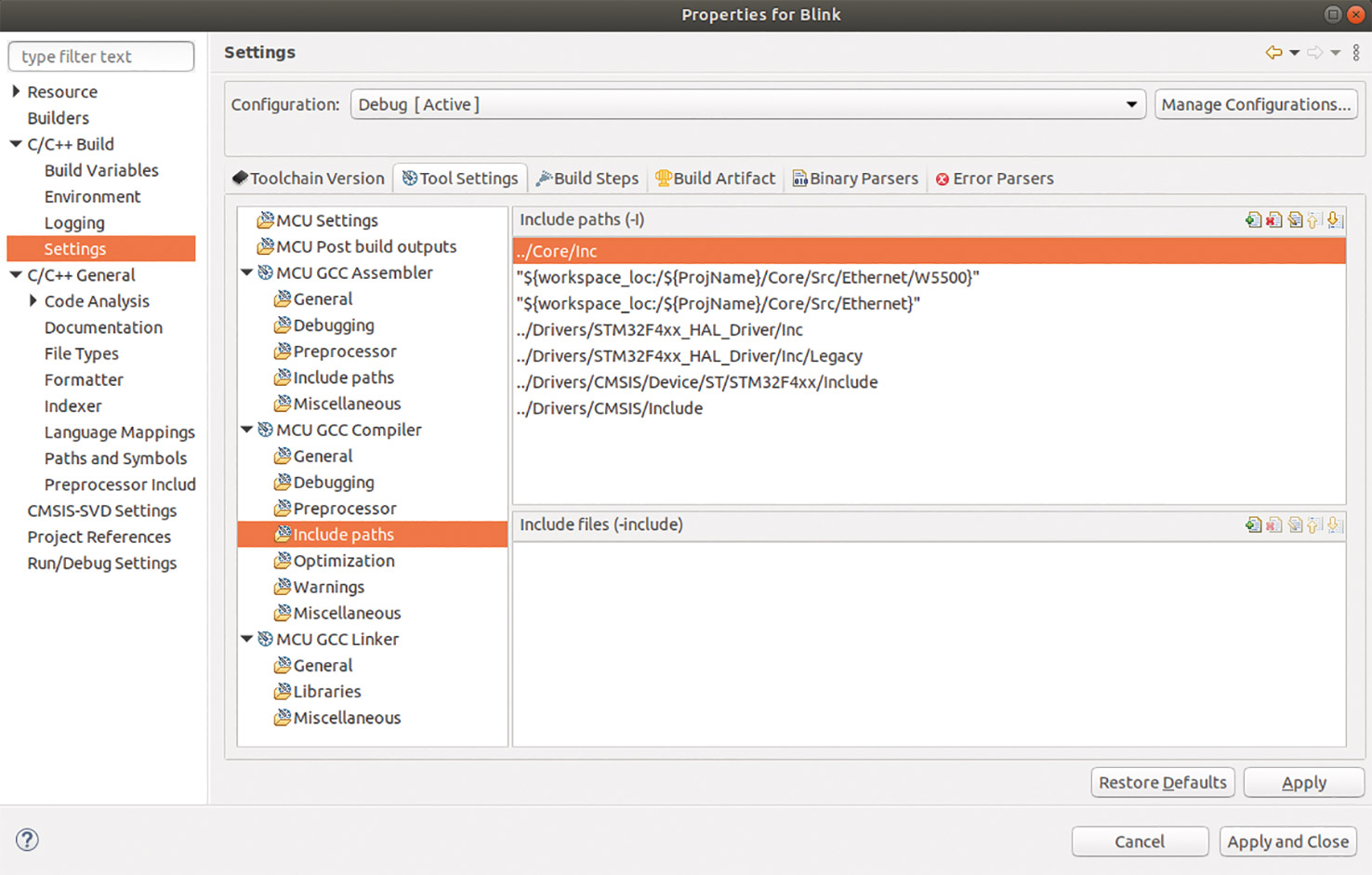
Now we have to include the library into the project. Use the right mouse button on the project in the STM32CubeIDE. Now follow the path to the configuration of the libraries Properties | C/C++ Build | Settings | Tool Settings | Include paths. Add the two paths Ethernet and Ethernet/5500 to Include paths (Fig. 8).
The library is now completely set up and included in the project. In the next section, we will show how to extend the project so that the Ethernet module can be used.
TO NEWSLETTER
Stay tuned on IoT’s latest News
Extend project
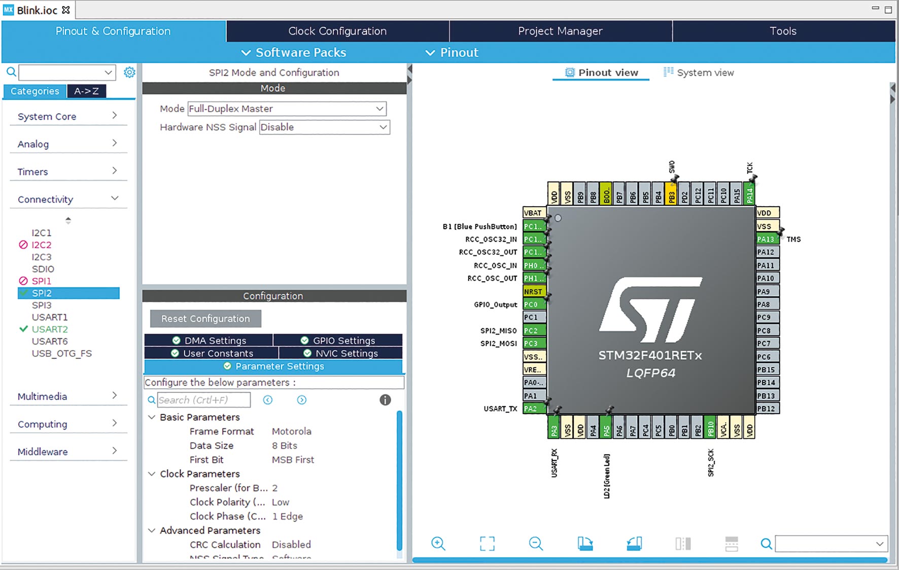
We now need to do some preliminary work on the project to include the WIZ5500 chip on the software side as well. Before we start to extend the actual source code, we have to configure the hardware of the project. That means that we activate the second SPI interface. We already connected the hardware at the beginning of the article. Open the Pinout & Configuration overview by clicking on the Blink.ioc file. Now select the SPI2 interface in the menu item Category | Connectivity and activate it in Full Duplex Master mode. Set the pin PC_4 to GPIO output. Use this pin as the chip select (CS) line for SPI communication. Figure 9 shows which pins of the STM32 have also turned green. In this case, green means that the pins are in use for the project.
If you click on Save, the IDE asks if we want to have the source code for the hardware configuration generated. It is not an easy task to create this code without errors, because the microcontrollers of the STM32 family offer so many possibilities – but there are also many possibilities to do something wrong.
In a few places, the IDE asks what it should do. In the beginning, it is important to read these questions and think about exactly what you want. After some time, you can make the IDE remember the answers. This will make work much smoother.
In Listing 3 we summarized the commands that you must include in the generated code to configure the WIZ5500. You can use the comments of the generator as a good guide. With these lines, the TCP-IP stack of the chip is activated, and it can already react to a simple ping. Please note that you are using a free IP from your local network. Of course, we must not forget to import the library for the WIZ5500. This can be done with the two import lines at the beginning of the program.
The communication between the library and our program runs via four special functions. These must be built into the source code of the main.c file. You can orientate yourself on the code generator comments. The functions control the CS signal and regulate over which SPI interface the data should run.
The last code block initializes the WIZ5500 and gives it a MAC and an IP address. When the program is loaded into the controller, it already responds to ping packets. Please test the connection first before you continue with the next steps.
Listing 3: Functions that must be included in the generated code
/* Private includes

----------------------------------------------------------*/

/* USER CODE BEGIN Includes */

#include "wizchip_conf.h"

#include "socket.h"

/* USER CODE END Includes */
/* Private user code
———————————————————*/
/* USER CODE BEGIN 0 */
void cs_sel() {
HAL_GPIO_WritePin(GPIOC, GPIO_PIN_4, GPIO_PIN_RESET);
}
void cs_desel() {
HAL_GPIO_WritePin(GPIOC, GPIO_PIN_4, GPIO_PIN_SET);
}
uint8_t spi_rb(void) {
uint8_t rbuf;
HAL_SPI_Receive(&hspi2, &rbuf, 1, 0xFFFFFFFF);
return rbuf;
}
void spi_wb(uint8_t b) {
HAL_SPI_Transmit(&hspi2, &b, 1, 0xFFFFFFFF);
}
/* USER CODE END 0 */
/* USER CODE BEGIN 2 */
uint8_t bufSize[] = {2, 2, 2, 2};
reg_wizchip_cs_cbfunc(cs_sel, cs_desel);
reg_wizchip_spi_cbfunc(spi_rb, spi_wb);
wizchip_init(bufSize, bufSize);
wiz_NetInfo netInfo = { .mac = {0x00, 0x08, 0xdc, 0xab, 0xcd, 0xef},
.ip = {192, 168, 3, 197},
.sn = {255, 255, 255, 0},
.gw = {192, 168, 3, 1}};
wizchip_setnetinfo(&netInfo);
/* USER CODE END 2 */
Web server
Now that we have a working network interface, we can start building the web server. The program source code is only shown in excerpts. You can download the complete project at Entwickler Magazin.
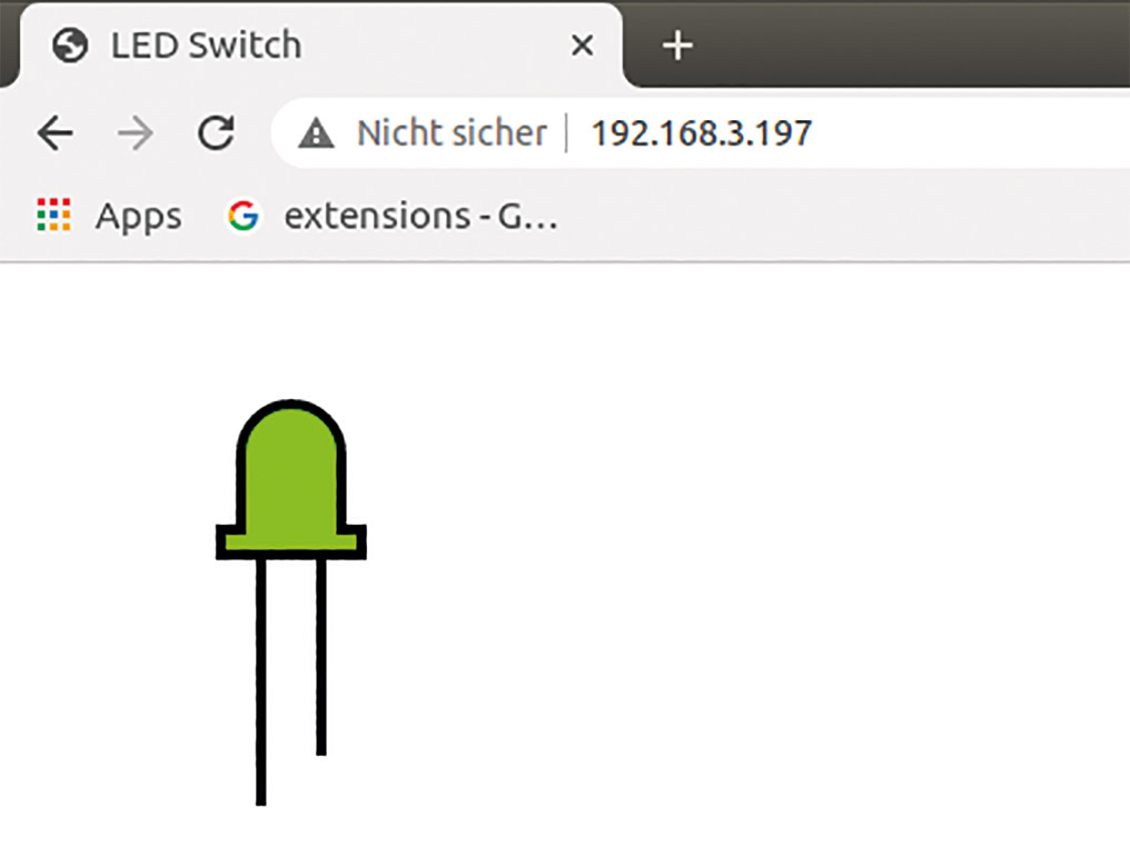
In order not to make things unnecessarily complicated, our web server can switch the LED installed on the Nucleo board on and off. Figure 10 shows how the small server presents itself. When the LED image is clicked, the browser sends an Ajax request to the server. The server changes the status of the LED and sends back the corresponding SVG graphic.
The libraries for building a web server are included in the project in the same way as the libraries for controlling the hardware. Copy the httpserver folder from the ZIP archive into your project and include it in the include path. Again, don’t forget to import it. As you can see in Listing 4, we import some more standard libraries that we need to be able to process strings.
The web server is relatively simple to use. It is initialized by calling the httpServer_init function. During initialization parameters like buffer and number of sockets are given. After that, the static HTML pages are registered with the function reg_httpServer_webContent. Here it is useful to outsource the HTML code to an external header file to make the code more readable. In the infinite loop, which normally contains the actual microcontroller programs, the httpServer_run function must now be called for each socket. The code snippet for this can be seen in Listing 4.
Listing 4: Initialize and run web server
/* Private includes

----------------------------------------------------------*/

/* USER CODE BEGIN Includes */

#include "wizchip_conf.h"

#include "socket.h"

#include "httpServer.h"

#include "webpages.h"

#include

#include "httpUtil.h"

#include

/* USER CODE END Includes */
/* USER CODE BEGIN 2 */
uint8_t bufSize[] = {2, 2, 2, 2};
reg_wizchip_cs_cbfunc(cs_sel, cs_desel);
reg_wizchip_spi_cbfunc(spi_rb, spi_wb);
wizchip_init(bufSize, bufSize);
wiz_NetInfo netInfo = { .mac = {0x00, 0x08, 0xdc, 0xab, 0xcd, 0xef},
.ip = {192, 168, 3, 197},
.sn = {255, 255, 255, 0},
.gw = {192, 168, 3, 1}};
wizchip_setnetinfo(&netInfo);
uint8_t socknumlist[] = {2, 3, 4, 5, 6, 7};
#define DATA_BUF_SIZE 2048
#define MAX_HTTPSOCK 6
uint8_t RX_BUF[DATA_BUF_SIZE];
uint8_t TX_BUF[DATA_BUF_SIZE];
httpServer_init(TX_BUF, RX_BUF, MAX_HTTPSOCK, socknumlist);
reg_httpServer_cbfunc(NVIC_SystemReset, NULL);
reg_httpServer_webContent((uint8_t *)”index.html”, (uint8_t *)index_page);
/* USER CODE END 2 */
/* Infinite loop */
/* USER CODE BEGIN WHILE */
while (1){
for(int i = 0; i < MAX_HTTPSOCK; i++)httpServer_run(i); // HTTP Server handler
/* USER CODE END WHILE */
It gets a little trickier if you want to have dynamic code. The generation of dynamic code is controlled by the two functions predefined_get_cgi_processor and predefined_set_cgi_processor. Note that the predefined_get_cgi_processor function is for HTTP GET calls and the predefined_set_cgi_processor function is for HTTP POST. How there is a set in the name, only the gods know. Believe me, this peculiar naming has already caused some confusion. Another important point when using dynamic code is that the called web pages must necessarily end in .cgi. This takes some getting used to, especially when using Ajax. The two functions can be seen in Listing 5.
Listing 5: The functions for generating dynamic content
/* Private user code

---------------------------------------------------------*/

/* USER CODE BEGIN 0 */

void cs_sel() {

HAL_GPIO_WritePin(GPIOC, GPIO_PIN_4, GPIO_PIN_RESET); //CS LOW

}

void cs_desel() {

HAL_GPIO_WritePin(GPIOC, GPIO_PIN_4, GPIO_PIN_SET); //CS HIGH

}
uint8_t spi_rb(void) {
uint8_t rbuf;
HAL_SPI_Receive(&hspi2, &rbuf, 1, 0xFFFFFFFF);
return rbuf;
}
void spi_wb(uint8_t b) {
HAL_SPI_Transmit(&hspi2, &b, 1, 0xFFFFFFFF);
}
uint8_t predefined_get_cgi_processor(uint8_t * uri_name, uint8_t * buf, uint16_t * len){
if(strcmp((const char *)uri_name, “led.cgi”) == 0){
HAL_GPIO_TogglePin (GPIOA, GPIO_PIN_5);
if(HAL_GPIO_ReadPin(GPIOA, GPIO_PIN_5)) {
*len = sprintf((char *)buf, led_on);
} else {
*len = sprintf((char *)buf, led_off);
}
}
return 1;
}
uint8_t predefined_set_cgi_processor(uint8_t * uri_name, uint8_t * uri, uint8_t * buf, uint16_t * len){
return 0;
}
/* USER CODE END 0 */
Even if you only want to use static HTML, you have to define at least the two functions empty, otherwise, the compiler will complain. The code in these two functions can become quite demanding. Therefore it makes sense to put them into extra files. The return code can be used to control whether the called CGI page could be generated (1) or an error occurred (0).
Concluding tips
I would like to give you a few general tips for programming web servers on microcontrollers. Microcontrollers have very limited resources, so you should use them sparingly. Graphics usually cost a lot of memory and then have to be transferred over the network to make matters worse. Use only small graphics if you absolutely have to, or always work with SVG, as shown in the sample program. It doesn’t matter if you embed the code directly in HTML or have it in a special file. The main thing is that it doesn’t take up a lot of memory in the controller. SVG graphics also have an enormous advantage since they can be enlarged without any loss of quality.
Source code that is the same on all pages, such as headers or footers, should be stored in the microcontroller’s memory only once, and not simply copied into each page for convenience.
Nowadays, no web application can do without dynamic content. Of course, our microcontroller can generate these as well. But, be careful not to generate complete web pages dynamically, but to update only small parts via Ajax. Ajax is our tool of choice since it does not require any additional libraries. You must always be aware that any cool JavaScript library must be placed in the microcontroller’s memory. Even the compressed jQuery already brings it to almost 90 kilobytes. The 512 kilobytes of the Nucleo are quickly gone—apart from the fact that it is no fun to include complete JavaScript libraries in a C program.
Caching is your friend in microcontroller programming. You should allow caching wherever possible.
Anything that could lead to excessive network traffic must be prevented. This may mean that you have quite a lot of functionality in the HTML/JavaScript – which is not bad at all, at least for the CPU usage of the microcontroller. Let everything that is possible be computed in the browser.
Conclusion
This article has shown how to add an Ethernet interface to an STM32 microcontroller. Due to the high flexibility of the STM32 microcontrollers some configuration is necessary to establish the connection between WIZ5500 and the STM32. This effort is limited to purposeful clicking when using the STM32CubeIDE. The Ethernet library of WIZNET seems a bit peculiar and also old-fashioned at first. But once you understand how it works, you can work well with it. All in all, it is easy to build a well-functioning web server on the STM32 using the tools shown here. Although the potential for errors in the project is high, it is a lot of fun to work with the Nucleo board and the STM32CubeIDE.


