
The abbreviation OTA stands for “Over the Air”. In our case, this means we supply the ESP32 with new software images through the WiFi interface. This kind of programming has a few advantages:
1- We don’t need annoying USB cables.
2- We can also program microcontrollers built into devices.
3- If you have several ESP32 in a project, you can assign them names so it’s easier to tell them apart.
4- Currently, some ESP32 development boards on the market have a small bug. You can only program them if you hold down the boot button while uploading. If we use OTA, this bug won’t happen at all.
5- Microcontrollers that aren’t soldered on a development board can be programmed with OTA without an additional USB adapter.
As you can see, there are many good reasons to look a little more intensively into OTA. But there is one small downside: With OTA, you cannot use debugging with the serial console. Although, it’s possible to use OTA and the serial console at the same time during the development phase, or you can switch the console to Telnet. In the following section, first, we’ll build a small test hardware so we can try out OTA right away on the live microcontroller.
TO NEWSLETTER
Stay tuned on IoT’s latest News
The hardware
Due to the Corona pandemic, it’s not easy to get ESP32 development boards right now. To make matters worse, there are currently quite a few boards in circulation with a small hardware error. Of course, if you have a working NodeMCU board, you can use it for our little experiment. In this article, we use the model ESP-32S, which has a few GPIOs less than the widely used NodeMCU board, but can be obtained at a reasonably fair price from Amazon. A double pack of boards currently costs 15.99€ [1]. A week ago, the price was still 14.99€, indicating that the chip shortage isn’t just in the automotive industry.
But let’s get back to the board itself, which already comes with cable connectors. This gives us the possibility of using the board without connectors. To be honest, I’m much more comfortable soldering the connectors myself than getting a board where they’re installed crooked. It’s extremely difficult to make connectors straight again. Unfortunately, this board also has the aforementioned hardware defect. This is relatively easy to fix with an additional capacitor between the ground and the EN input of the board. On the board there is an ESP32 with a CE marking, meaning we can use it in the EU with a clear conscience. You can see the development board’s pinout in Figure 1. As you’ve probably noticed, the manufacturer didn’t pay attention to numbering.
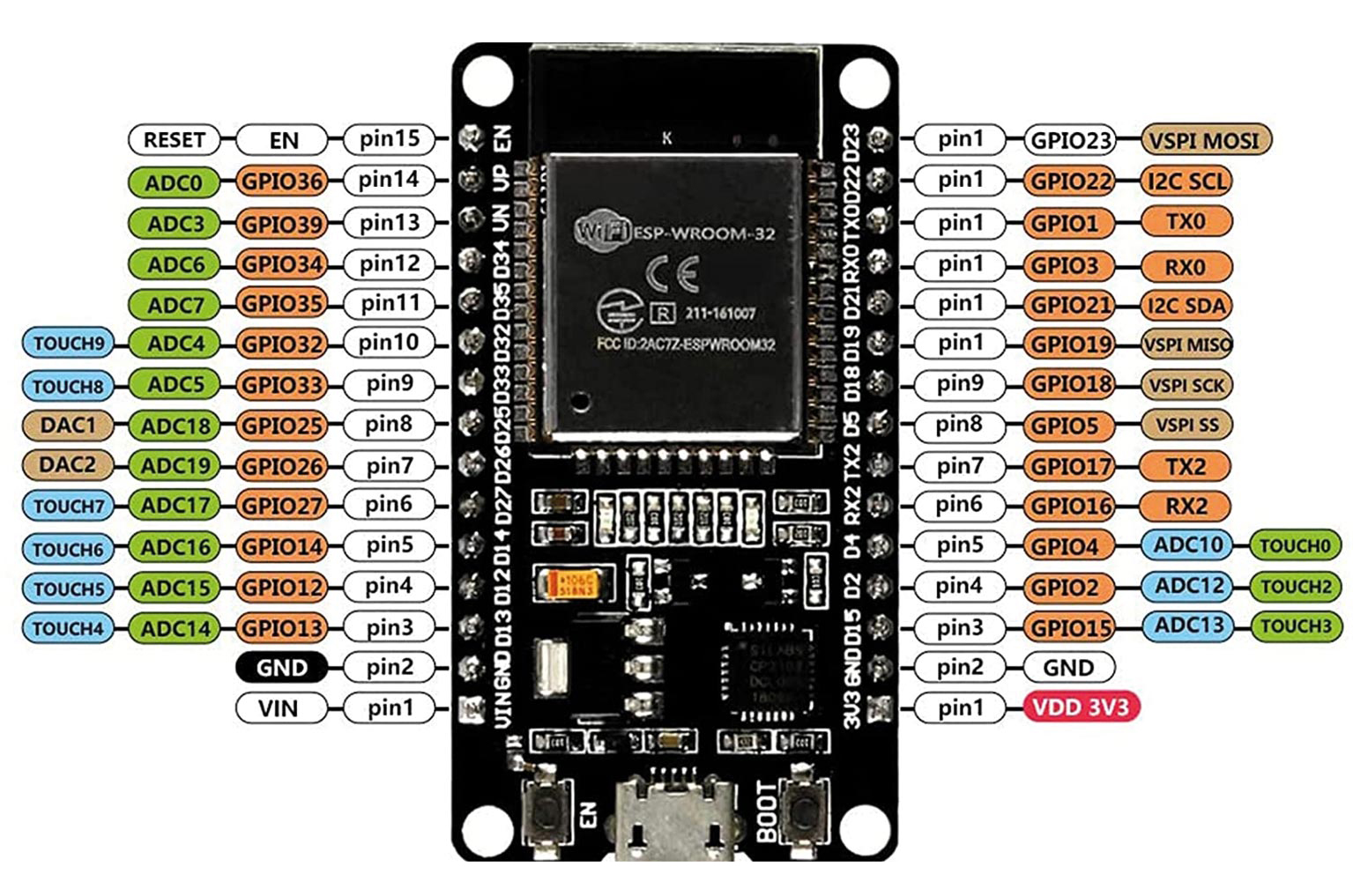
Fig. 1: ESP-32S development board pinout
To get an idea of what an ESP32 can do, take a look at Table 1. It summarizes the microcontroller’s most important technical data. To put it briefly: You get a lot of functionality for a small price.
| ESP32 technical data |
| 240 MHz Dual Core Tensilica LX6 MicroController with 600 DMIPS |
| 520 KB SRAM |
| 802.11BGN HT40 Wi-Fi Transceiver |
| Dual mode Bluetooth |
| 16 MByte Flash |
| 2.2V to 3.6V operating voltage |
| -40°C to +125°C operating temperature |
| Hall Sensor |
| 10x Capacitive Touch Interface |
| 32 kHz Crystal Oscillator |
| 32x GPIO |
| 3x UARTs |
| 3x SPI |
| 2x I2S |
| 12x ADC |
| 2x DAC |
| 2x I2C |
| PWM/Timer Input/Output to allGPIO Pins |
| SDIO Master/Slave 50 MHz |
| External SPI Flash up to 16 MB |
| SD-Card Interface Support |
| WEP, WPA/WPA2 PSK/Enterprise |
| Hardware accelerated Encryption: AES/SHA2/Elliptical Curve Cryptography/RSA-4096 |
| Supports Sniffer, Station, softAP and Wi-Fi Direct Modes |
| Max Data Rate of 150 Mbps@11n HT40, 72 Mbps@11n HT20, 54 Mbps@11g, and 11 Mbps@11b |
| Maximum Transmit Power of 19.5 dBm@11b, 16.5 dBm@11g, 15.5 dBm@11n |
| Minimum Receiver Sensitivity of -98 dBm |
| 135 Mbps UDP sustained Throughput |
| 2.5 μA Deep Sleep Current |
Table 1: ESP32 technical data
To work with the board, plug the ESP32 onto a breadboard. More accurately, there are two breadboards cleverly connected to each other. Pin spacing is so high on ESP32s so you won’t get far with just a single one. Connect an LED bargraph with the suitable series resistors (1 KOhm) to the ESP32 outputs. This is simply better suited for these kinds of test setups than individual LEDs. For one, it takes up less space and it just looks neater too. Finally, we shouldn’t forget the additional capacitor that lets us load programs into the ESP32 without needing to hold down the boot button. To make it easier, Figure 2 shows a sample circuit diagram. For the first steps, we supply the test setup with voltage from the[1] USB interface. Later, we can switch to any other 5V voltage source that we’ve connected to the ESP32 board’s VIN pin.
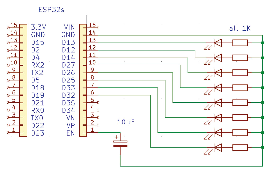
Fig. 2: Circuit diagram for test setup
The Arduino IDE
The Arduino IDE is a free development environment for microcontrollers that you can download for the usual operating systems from the homepage [2]. After the installation is finished, please start the IDE (if it has not already started automatically). The IDE is best suited for developing programs for the ESP32. It was originally developed for software development with Arduino boards, but it can be adapted for any microcontroller with the use of board managers. In order to download the board manager for the ESP32 development board, first we need to enter an additional board manager URL, which is stored in the IDE’s settings. To do this, navigate with the menu to the appropriate place (FILE | PREFERENCES | ADDITIONAL BOARD MANAGER URLs). The edit button is behind the text field, which makes sense to use. With the second board administrator URL, working over the simple text field becomes unwieldy. Add the following URL to the board administrators:
https://dl.espressif.com/dl/package_esp32_index.json
Now we can install the board manager. The URLs only tell the IDE where to additionally search. To install the board manager, navigate from the menu (TOOLS | BOARD: “<ANY_BOARDNAME>” | BOARD MANAGER…) to the appropriate place. You can search here for the ESP32 (Fig. 3). Select the board administrator from Espressif Systems and install it. Depending on how good your internet connection is, the download may take a while. When the installation is finished, please close the window and select your board from the menu. (TOOLS | BOARD | ESP32 ARDUINO | Node32s) The board presented in the hardware section is named “ESP32s” in the Arduino IDE. If you used another board, enter the board here.
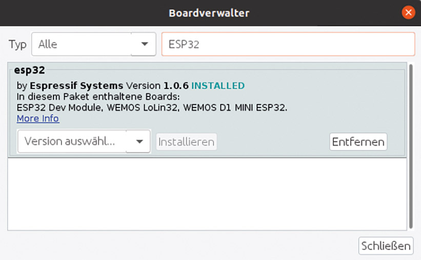
Fig. 3: Installing the board manager for the ESP32
The blink example
For a first test run, let’s load a simple example program into the ESP32. First, we must connect our test setup to the PC via USB. Linux users are fine here because the USB interface driver is already available. Windows users need to install a corresponding driver [3]. After installation, an additional COM port appears. You need to specify this in the Arduino IDE as the upload port (TOOLS | PORT). Here, Linux users simply choose /dev/ttyUSB0. For testing, we select the good old blink program. Select the example from the menu (FILE | EXAMPLES | 01.BASICS | BLINK) so that we don’t have to type the source code. Clicking the upload icon will load the blink program (Listing 1) into the ESP32. If you aren’t using the ESP32 suggested board, please be aware that not all ESP32 development boards have a built-in LED. If you get an error message stating that the LED_BUILTIN doesn’t exist, use a GPIO pin that’s already connected to an LED by the test setup. The test has succeeded when an LED flashes every second.

Listing 1: Blink example
void setup() {
pinMode(LED_BUILTIN, OUTPUT);
}
void loop() {
digitalWrite(LED_BUILTIN, HIGH);
delay(1000);
digitalWrite(LED_BUILTIN, LOW);
delay(1000);
}
OTA in Detail
After we’ve set up a working test environment with the ESP32, we can begin looking at OTA a little more intensively. First of all, you should be aware that OTA support isn’t part of the ESP32 bootloader. Rather, it’s an additional piece of software that runs in the microcontroller. That means that we need to make sure the image we upload contains code for OTA support. Additionally, we still need to use the USB interface for our very first OTA image upload. In the next step, we’ll add OTA support to all further images, ensuring smooth uploading in the future. Another important point is that the ESP32 needs to be on the same IP network as the Arduino IDE. If this isn’t the case, then the network interfaces for uploading the code won’t appear in the IDE.
So far, so good. Now let’s try and see how we can create a program with OTA support. Of course, the Arduino IDE has a simple example of this that we can use as a template. The template can be found under the examples for the Node32s board (FILE | EXAMPLES | EXAMPLES FOR Node32s ARDUINOOTA | BASICOTA). Now the access data for the respective network must be added in the example code. The ESP32 should also be assigned a unique name here—if we don’t, then it will receive an automatically generated, extremely cryptic name. I can say from experience that with two microcontrollers, automatically generated names already cause confusion. Assign a name for the ESP32 by commenting the line ArduinoOTA.setHostname(“myesp32”), and selecting a suitable hostname. For our first attempt, the hostname from the example is perfectly sufficient.
Now you can upload the code like in the Blink example. The only thing we see after uploading is that the LED stopped blinking. Currently, we’ve only uploaded the bare OTA support into the ESP32, without a program of our own. Now you should have an additional network port to choose from, which you can use to upload programs to the ESP32. This is shown in Figure 4. The port is named myesp32.
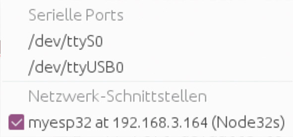
Fig. 4: Network ports in the Arduino IDE
To test the network interface, the existing program should be adapted so that test results can eventually be seen. For this, we’ll run a simple light over the bargraph and go into a few aspects that should be considered when programming the ESP32. Let’s start with the fact that it makes sense to name the program’s GPIO pins. The #define directive is our method of choice, since the defined values are built into the code by the preprocessor before the actual compilation run. The procedure produces fast, memory-optimized code. The code fragment can be seen in Listing 2. Include the instructions directly after the #include block. The commands from Listing 3 need to be added at the end of the function setup();. These make sure that we can use the GPIOs as digital outputs. Listing 3 shows the loop(); function. Two additional variables that we need for the program are defined in front of this.
Listing 2: Defining plain text names
#include <Mywlan.h>
#define LED0 13
#define LED1 12
#define LED2 14
#define LED3 27
#define LED4 26
#define LED5 25
#define LED6 33
#define LED7 32
Listing 3: Define the GPIOs’ functionality
pinMode(LED0, OUTPUT);
pinMode(LED1, OUTPUT);
pinMode(LED2, OUTPUT);
pinMode(LED3, OUTPUT);
pinMode(LED4, OUTPUT);
pinMode(LED5, OUTPUT);
pinMode(LED6, OUTPUT);
pinMode(LED7, OUTPUT);
Before we look at Listing 4 in more detail, let’s briefly review microcontroller programming in general. Code in the setup(); function is executed only once when the microcontroller is started. It will start again when exiting. The microcontroller needs a little time to manage itself between exiting and starting the loop(); function. WLAN connections are established and maintained here, for example. If a modern microcontroller like the ESP32 doesn’t have time to self-manage, it crashes quickly. So all programs in the loop(); function need to work cyclically, meaning that individual program parts will check if there’s something to do and immediately terminate themselves. There can also be no infinite loops or long waiting times within loop();. You must be asking yourself how the blink example works at all. The reason is that the delay(); function always gives the microcontroller the chance to manage itself during the waiting time. ESP32 beginners in particular fall into this trap because they aren’t aware of the issue from other microcontrollers, such as the Arduino. Now that we know the context, it’s clear why the program in Listing 4 looks so unusual.
Listing 4: Code for the running light
int old=0;
int counter=0;
void loop() {
ArduinoOTA.handle();
if ((old/500)<(millis()/500)){
old=millis();
switch (counter++%8){
case 0:digitalWrite(LED0,HIGH);digitalWrite(LED7,LOW);break;
case 1:digitalWrite(LED1,HIGH);digitalWrite(LED0,LOW);break;
case 2:digitalWrite(LED2,HIGH);digitalWrite(LED1,LOW);break;
case 3:digitalWrite(LED3,HIGH);digitalWrite(LED2,LOW);break;
case 4:digitalWrite(LED4,HIGH);digitalWrite(LED3,LOW);break;
case 5:digitalWrite(LED5,HIGH);digitalWrite(LED4,LOW);break;
case 6:digitalWrite(LED6,HIGH);digitalWrite(LED5,LOW);break;
case 7:digitalWrite(LED7,HIGH);digitalWrite(LED6,LOW);break;
} //switch
} //if
} //loop
Let’s start with the ArduinoOTA.handle(); function. It needs to be called cyclically, or else the ESP32 will crash. Therefore, the rest of the code in loop(); is also written to work cyclically. The if implements a timer with the help of the millis(); function, which executes the enclosed code every 500 milliseconds. With each run, the counter variable is incremented by 1. Since the case commands expect numbers from 0 to 7, we apply the modulo operator to the counter variable to receive these values. The individual case commands switch the LEDs on and off, creating a running light effect. The time has come to transfer our program over to the ESP32 for the first time with the OTA interface. For this, select the newly added network interface under TOOLS | PORT and press the button to upload it. The output looks a little different than when uploading via USB. After a short wait, our new program starts automatically—it’s so easy to program the ESP32 with OTA over the WLAN interface.
OTA tips
The example from the previous section works well, but it’s a bit unwieldy. So, we’ll outsource the complete code for setting up OTA into a function stored in an extra file. Import this file and call just the function. This way, only one call is needed in our actual program. The OTA code is hidden. And since we’re on the subject of outsourcing: Writing the connection data for your own WLAN into the source code is clumsy. One careless commit, and login data is on the Internet. [2] If we put the credentials in an extra file and move it to the Arduino IDE’s library directory, it can be accessed from all projects as the library directory isn’t part of a project. So, there isn’t a possibility of unintentionally revealing any passwords. In order to create a file with login data for the WLAN, change to the Arduino IDE’s libraries folder (by no means change to lib—here are the IDE’s Java libraries). Create a folder there called Mywlan. In this folder, create a file named Mywlan.h and write the following two #define statements in the file:
#define MYSSID “<YOUR_SSID>”
#define MYPASSWORD “<YOUR_PASSWORD>”
Now you can import the file #include <Mywlan.h> in all your programs and access the values:
const char* ssid = MYSSID ;
const char* password = MYPASSWORD ;
Of course, you can also use this file to save other global settings you use in all programs. When we work with OTA, first the program is loaded into a cache—the program is only activated once this process is complete. If an error occurs, then the program’s older version stays active. The cache—and the OTA software itself—occupy memory space in the ESP32, so naturally, there’s less left for our programs. You should always keep this fact in mind. If you run out of memory at some point, you can save a lot by disabling OTA. Fortunately, the ESP32 is quite generous with memory out of the box, so we won’t run into this limit anytime soon.
OTA only works if the ESP32 continuously reports to the Arduino IDE over WLAN. At first, this isn’t a problem, but we have to be aware that the microcontroller has a high power consumption because of this. For applications that work with batteries or need to save energy, OTA isn’t the optimal solution for a permanent operation. But even in these cases, OTA can be used for development and an image without OTA can be used in later live operations. If you’re working alone in your basement, it’s probably not an issue, but you should know that the OTA interface can also be password protected. If this interests you, take a closer look at the commented out lines in the sample code.
Conclusion
For everyone who likes to work with microcontrollers and the Arduino IDE, OTA is an interesting affair. In this article, we’ve shown how OTA works using the ESP32 as an example—but this doesn’t mean that it only works for the ESP32. Many microcontrollers can be programmed with OTA. Especially in projects where several microcontrollers work together, the OTA interface is a real relief. Finally, I wish you a lot of fun with your projects using the ESP32 and OTA.
Links & Literature
[1] ESP32 Development Board: https://www.amazon.de/gp/product/B093GTDY9H
[2] Download Arduino IDE: https://www.arduino.cc/en/software
[3] Windows Driver: https://www.silabs.com/developers/usb-to-uart-bridge-vcp-drivers